Any camera we attach to a spectrograph will not have the same sensitivity to all wavelengths of light. To correct for these, we need to illuminate the spectrograph with a light source that does not have any absorption or emission lines. Ideally, it would emit light with the same intensity (power per unit area per wavelength interval) over the entire range of wavelengths. Unfortunately, there are no light sources that do this over the range we are interested in. The closest we can come is from a hot incandescent filament in a halogen bulb. If we know the temperature of the filament, then later, we can correct for the dependence of intensity on wavelength using the Planck relation for blackbody radiation.
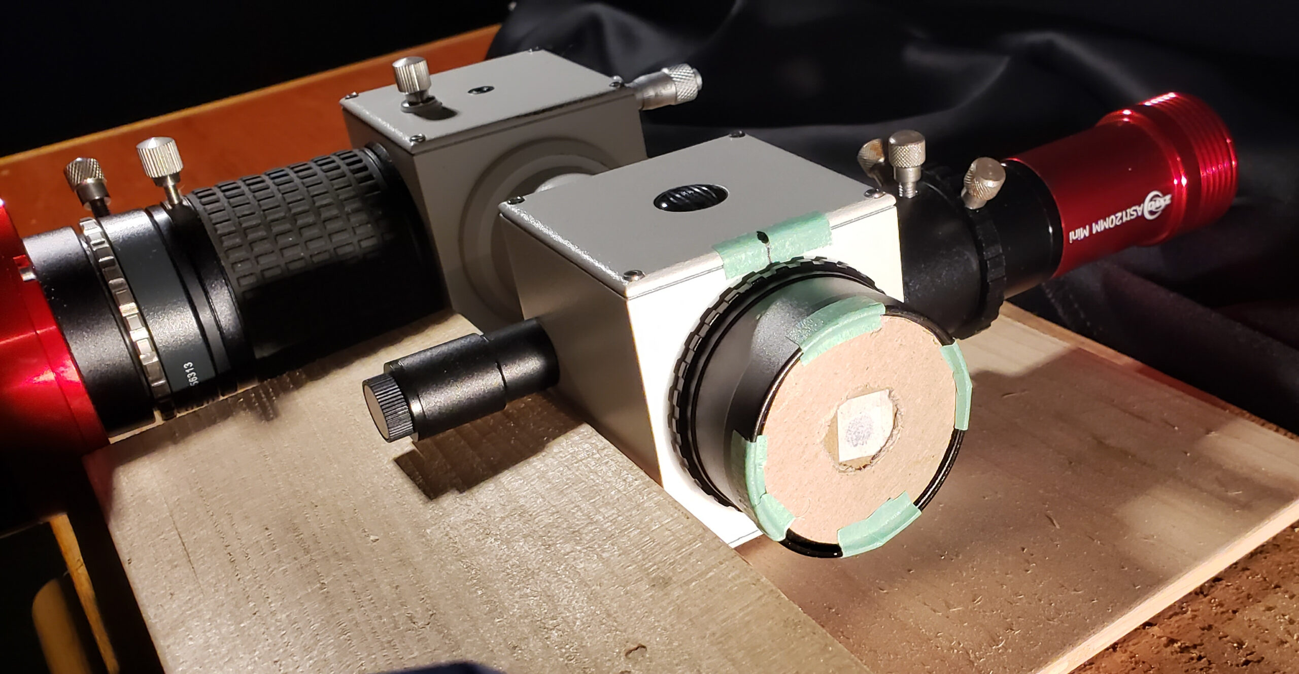
Following section 7.4 The acquisition of the “flat-field” source in the specINTI documentation, I did this procedure on my workbench. I cut out a circular disk of cardboard to fit over the entrance of the spectrograph. In the center of the disk, I cut out a circle of diameter 5.6 mm and glued a thin piece of tissue paper over the hole. In the photo, you can see the cardboard disk with the tissue paper diaphragm leaning against the guidescope port. The purpose of making a 5.6 mm diaphragm was to simulate the telescope aperture.
The measured aperture D of my telescope is 248 mm and the effective focal length F with the spectrograph is 2927 mm, so F/D = 11.8. The distance between the spectrograph slit and the diaphragm is 66.5 mm, so the diameter of the hole should be (66.5 mm) / 11.8 = 5.6 mm.

Here you see the diaphragm secured over the entrance to the spectrograph.

The halogen lamp is situated far from the diaphragm (many times the width of the hole) to ensure uniform illumination.

It seems to be important to combine many flat frame images when preparing a master flat frame. The image below is the result of combining 150 individual frames, each with an exposure time of 1.0 second. I’m not sure why a large number of frames works so much better, but in my experience, using only a half-dozen or so flat frames gives a unreasonable result when the stellar spectrum is divided by the master flat frame.

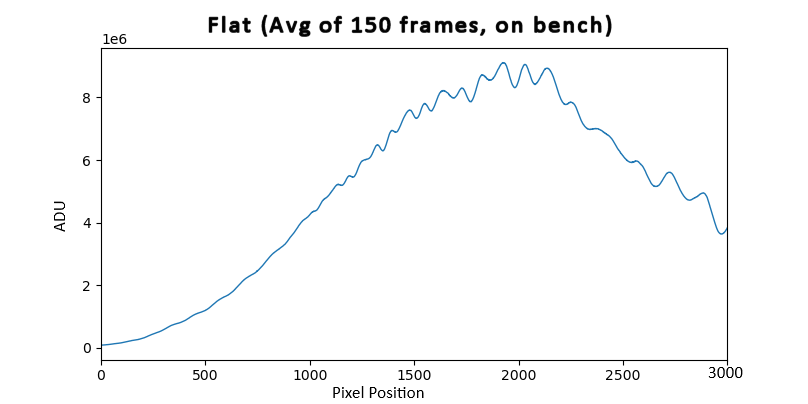
There are two things to note about the master flat frame above: first, it clearly shows that the greatest response to incident light is about two-thirds of the way from the left edge, at pixel positions around 2000. Second, there are alternating light and dark bands along the horizontal axis.
An explanation of the bands is in the specINTI documentation of section 9.8 Back to the flat-field. Apparently, it is the result of the technology used to manufacture CMOS sensors.
While it is not necessary for the workflow, it is nevertheless instructive to view the profile of the master flat frame, which is shown below. This was obtained by using Object binning feature in vSpec and saving it in .fits format which was then opened in the specINTI Editor under the Profile display.

In any case, we need to apply the master flat field to our spectral images of Alfirk, which I believe amounts to dividing our raw profile by the flat profile. To see the result of applying dark, offset (bias) and flat frames to our raw profile, please return to the Workflow page.